Monday 9 July 2018

How cardholder data can be stolen before it reaches the Merchant

In a couple of recent attacks cardholder data has been stolen even before it entered the merchant's or payment processors systems. In fact it is stolen from within the browser the cardholder was using to enter their payment card details. This attack, even although the card data theft is not actually occurring in a merchant's system is the result of a security weakness with the merchant's security.

The attack is a Cross Site Scripting Inclusion (XSSI) attack and on a simply level it occurs where a payment page has a link to a script hosted on another domain that provides functionality the merchant required. Due to the nature of how the script is called, it bypasses the principle of the same-origin policy and allows the script which is from a different domain to the hosted page, to read the document object model (DOM) of the page it is called from, giving it the ability to read the contents of forms such as those contain card holder data. If that script is malicious or compromised through a security failing on the part of the provider who is hosting it then the merchant's page is compromised. The merchant's security failure is failing to recognizing the risk of using an external hosted script and ensuring it is secured. There are techniques such as Sub-Resource Integrity (SRI) that can be used to determine if a called script has been compromised through the use of cryptographic hashes. Additionally the supplier of the script is part of the supply chain and the security of the script and hosting paltform should be part of the due diligence checks on the supplier.

A typical attacker scenario would be an attacker looking to compromise card data will find a merchant with payment page, examine the source code and DOM of the page using a web proxy and other tools and identify the use of an externally hosted script. The attacker will then examine the security of script hosting platform and if possible compromise any vulnerabilities and replaced the existing script with a malicious script designed to scrape the payment forms and send the harvested data to systems the attacker has access to, often other compromised systems.

The flow of the attack is described below
1)     Attackers compromised the 3rd party’s server through a vulnerability and replace scripts on that server that are used by merchants with malicious code.
2)     A cardholder clicking on checkout caused their browser to request the payment page to be called from the merchant’s server.
3)     The page contained a link to the 3rd party’s hosted JavaScript is rendered in the browser the link is executed and the browser requests the JavaScript
4)     The previously compromised script is loaded from the 3rd party’s server and executed in the browser
5)     As cardholder details are entered in to the fields within the payment form the malicious script reads them and sends them to the attacker’s server

The scenario and diagram show how XSSI can be used to compromise data in a browser rather than a merchants own systems and often through a system that does not belong to the merchant. It shows how attackers are looking at end points where security may be lower than an internal system owned by a merchant. Merchants recognize having an internal systems processing card data is at high likelihood of being attacked and outsource payment processing using techniques such as silent order posting to send data direct from a form within a browser to the payment processor but a simple script can provide the foothold an attacker needs to steal payment cards before reaching the merchant or payment processor.

Thursday 12 April 2018

PCI DSS: Are you meeting the new mandatory requirements.

On the 31st January 2018 a number of the requirements in the PCI DSS v3.2 become mandatory; which means since that date you should have the relevant controls in place to meet those requirements. The standard requires for the controls to be in place from at least the end of January and not left until your certification renewal date.
For all organisations you should have implemented the following if applicable

  • Requirement 6.4.6 requires your change management processes be enforcing that upon the completion of a change, all relevant PCI DSS requirements on any in-scope system, process or documentation has been updated as applicable 
  • Requirement 8.3.1 requires all administrative access to the CDE across your own network should have multi-factor authentication (MFA) in place that meets the requirements of the PCI DSS. The SSC have published a guide on the use of MFA, the implement MFA should be using at least two out of the three authentication methods and not the same method twice and there needs to be independence between the authentication methods used.

For service providers the following should be in place if applicable

  • Requirement 3.5.1 requires a documented description of your cryptographic architecture that details all the algorithms, protocols and keys used to protect the storage of card data that includes details such as the key strength and expiry dates of keys and certificates. It should detail what the keys are used for to ensure the correct strength keys are being applied and you need an inventory of all components used in protecting keys ie Secure Cryptographic Device (SCD) or hardware security module (HSM).
  • Requirements 10.8 and its sub requirement 10.8.1 require a policy, procedure and process in place to detect and respond to failures in your critical security controls, a list of common critical security controls is given in the requirement, but the list is not definitive and other security controls such as patching should be monitored. The response should include how security functions are restored, documented, analysed, risk assessed, remediation requirements and lessons learnt.
  • Requirement 11.3.4.1 requires service providers to perform penetration testing on segmentation controls; if there are used; at least every six months. All service providers will need to of completed a penetration test of their segmentation controls within six months of the requirement becoming effective and August 1, 2018. 
  • Requirement 12.4.1 requires the establishment of a PCI compliance programme with responsibilities for the programme defined, it should also define how the executive management are informed of the state of the compliance programme by periodic updates. There is a requirement for a charter document to cover the establishment of accountability and communication to the executive management that is signed by the executive management.
  • Requirement 12.11 requires you to be holding at least quarterly reviews to confirm personal are following security policies and operational procedures.  It is now coming up to 3 months after deadline when the requirement became mandatory. Have you held you first review yet? Your compliance status is in jeopardy if you haven’t. A QSA conducting a RoC on a service provider is expecting to see evidence of the quarterly reviews since 31st January 2018 for you to be compliant even if the audit is being conducted in December of this year.


Thursday 29 March 2018

PCI DSS requirement 10.8 and physical hosting services

One of the now mandatory requirements since 31 January 2018 of the PCI DSS standard is requirement 10.8 which requires service providers to implement a process for the timely detection of failures of critical security controls systems. Historically service providers that just provide a physical hosting service where they provide the physical space for a client to put their own equipment in and the service provider gives physical security, power and internet connection to the empty racks have certified to meeting just requirements 9 and 12 of the PCI DSS and their clients are responsible for all the other requirements. Since the end of January service providers should also be implementing processes where the access control systems are monitored to provide timely detection of failure.

A common failure of CCTV is where the storage of recordings to meet the 3 months requirement (9.1.1) is based on the frequency of triggering of the camera and the resulting clip being saved to disk, the issue occurs when the frequency is higher than expected and the disk space is used quicker than estimated and roll around occurs before the end of the 90 day period with new files overwriting the oldest files such the 90 storage period is not meet causing a failure of the access control system to meet the requirements. A hosting provider can implement a check on CCTV access control systems for the oldest date of recording and ensure this exceeds the storage requirements either programmatically or by physically viewing the oldest clip for each of the cameras.

Monday 15 May 2017

Raspberry Pi based Radio Alarm Clock (part 2 updated)

As part of the project I wanted to use the networking features of the Raspberry Pi Zero W to enable it to stream internet radio as well as the possibility of playing mp3 files from a network share.

The Zero is only a single core CPU as opposed to the Pi 3 which is quad core, also the memory is 512MB not the 1GB of the Pi 3. This means the computational resources are less but still capable.

As I will be using various display boards and controllers attached via the GPIO header I didn't need the full Pixel desktop graphics. This mean't the board would be configured to be a headless node with SSH access.

After creating a SD card with the operating system to which their are plenty guides I updated the the OS to ensure I was using the latest version.

sudo apt-get update
sudo apt-get upgrade

I also configured Pi to boot into command line and enabled SSH, not forgetting to change the default password. Finally I enabled the I2C interface which is required for the MicroDot Phat, OLED display and the RTC I am going to use.

Configuring the HATs and hardware


There are a number of HATS (or Bonnets) that I'm using along with some additional hardware, these require some libraries to get them working. There are plenty of examples vendors websites and on the Internet, however some pointers.

Real time clock


Using the Adafruit DS3231 Precision RTC Breakout as the RTC in this project. Installation instructions can be found on their website "Adding a Real Time Clock to Raspberry Pi"

The main steps for configuration are

Verify Wiring (I2C scan)

sudo i2cdetect -y 1

Should show and entry for 0x68

Once you have the Kernel driver running, i2cdetect will skip over 0x68 and display UU

You can add support for the RTC by adding a device tree overlay. Run the following command

sudo nano /boot/config.txt

Add dtoverlay=i2c-rtc,ds3231 to the end of the file/ Save it and run sudo reboot to start again.

Log in and run sudo i2cdetect -y 1 to see the UU show up where 0x68 would of been previously

i2cdetect results

Micro Dot pHAT


There is an excellent getting started tutorial for the Micro Dot pHAT  tutorial on the Pimoroni website (https://learn.pimoroni.com/tutorial/sandyj/getting-started-with-micro-dot-phat)

The software library is available at https://github.com/pimoroni/microdot-phat however they provided an excellent install script. Open a new terminal, and type the following, making sure to type 'y' or 'n' when prompted:

curl https://get.pimoroni.com/microdotphat | bash

Stereo Amplifier Bonnet


Adafruit provide an excellent range of support material and there is a Adafruit tutorial for the Stereo bonnet (https://learn.adafruit.com/adafruit-speaker-bonnet-for-raspberry-pi). Again there is a good install script, open a new terminal, and type the following, making sure to type 'y' or 'n' when prompted:

curl -sS https://raw.githubusercontent.com/adafruit/Raspberry-Pi-Installer-Scripts/master/i2samp.sh | bash

OLED display


The display is a more traditional process for installation and for this project as the board is less of a mainstream manufacturers device I went for Luma OLED library and as it worked I'm sticking with it for this project. Open a new terminal, and type the following

$ sudo apt-get install python-dev python-pip libfreetype6-dev libjpeg-dev
$ sudo -H pip install --upgrade pip
$ sudo apt-get purge python-pip
$ sudo -H pip install --upgrade luma.oled
$ git clone https://github.com/rm-hull/luma.examples.git
$ sudo -H pip install -e .

Sound utilities


There are a lot of choices for playing sound files and streaming audio, I use two players.

mp3 player


I went for a wll established play the MPG123 which had a number of features that made it attractive and it worked so didn't go looking for the perfect player. to install ,pg125 open a new terminal, and type the following

sudo apt-get install -y mpg123

The big problem with the sound HAT I used and the sound utilities is that is difficult to software control the volume. In order to get volume control working I had to configure a volume controller.

To do this I needed to create a new softvol device, using speakerphat as device name and Master as the control name. Using Master as sound card does not have a master volume control

To determine if name has been used for an existing control already, it shouldn't exist if you are following these instructions I check for any existing audio controls using the following.

amixer controls | grep Master

As it didn't find a control called Master it made following some of the available tutorials a bit easier. What I found I had to do to get this all worming was to create some configuration files.

create ~/.asoundrc

pcm.softvol {
 type softvol
 slave {
  pcm "speakerphat"
 }
 control {
  name "Master"
  card 0
 }
}
pcm.!default {
 type plug
 slave.pcm "softvol"
}

create /etc/asound.conf

pcm.!default {
 type plug
 slave.pcm "speakerphat"
}

ctl.!default {
 type hw card 0
}

pcm.speakerphat {
  type softvol
  slave.pcm "plughw:0"
  control.name "Master"
  control.card 0
}

After which it was possible to use amixer to set the volume of the play back.

Additional software


In addition to the above software I also installed some additional components that could be helpful in later additions of the devices.

As part of the software to drive this I'm considering a web based GUI to enable easier setting of alarms and editing playlists. To that end I have installed a lightweight database and web server

I have gone for SQLITE3, Lighttpd, and PHP5 again there are a lot of tutorials on the installation and use of this combination of software on the internet.

sudo apt-get -y install lighttpd
sudo apt-get -y install sqlite3
sudo apt-get -y install php5 php5-common php5-cgi php5-sqlite

sudo lighty-enable-mod fastcgi
sudo lighty-enable-mod fastcgi-php

sudo service lighttpd force-reload

sudo chown -R www-data:www-data /var/www
sudo chmod -R 775 /var/www

sudo usermod -a -G www-data pi

sudo reboot

To test the software I used the following files placed into /var/www/html

test.php

<?PHP
phpinfo()
?>

testdb.php

<?php
try {
    // Create file "scandio_test.db" as database
    $db = new PDO('sqlite:scandio_test.db');
    // Throw exceptions on error
    $db->setAttribute(PDO::ATTR_ERRMODE, PDO::ERRMODE_EXCEPTION);
  
    $sql = <<<SQL
CREATE TABLE IF NOT EXISTS posts (
    id INTEGER PRIMARY KEY,
    message TEXT,
    created_at INTEGER
)
SQL;
    $db->exec($sql);
  
    $data = array(
        'Test '.rand(0, 10),
        'Data: '.uniqid(),
        'Date: '.date('d.m.Y H:i:s')
    );
  
    $sql = <<<SQL
INSERT INTO posts (message, created_at)
VALUES (:message, :created_at)
SQL;
  
    $stmt = $db->prepare($sql);
    foreach ($data as $message) {
        $stmt->bindParam(':message', $message, SQLITE3_TEXT);
        $stmt->bindParam(':created_at', time());
  
        $stmt->execute();
    }
  
    $result = $db->query('SELECT * FROM posts');
  
    foreach($result as $row) {
        list($id, $message, $createdAt) = $row;
        $output  = "Id: $id<br/>\n";
        $output .= "Message: $message<br/>\n";
        $output .= "Created at: ".date('d.m.Y H:i:s', $createdAt)."<br/>\n";
  
        echo $output;
    }
  
    $db->exec("DROP TABLE posts");
} catch(PDOException $e) {
    echo $e->getMessage();
    echo $e->getTraceAsString();
}
?>

Configuring Lighttpd


To configure Lighttpd to support Python as a CGI language the lighttpd.conf needs to be updated to include the cgi module. This requires the following entry into the lighttpd configuration file (/etc/lighttpd/lighttpd.conf) in the server.modules section

            "mod_cgi",

At the end of the configuration file add the following

$HTTP["url"] =~ "^/cgi-bin/" {
        cgi.assign = ( ".py" => "/usr/bin/python" )
}

The lighttpd daemon will need to be restarted using the following command

sudo service lighttpd force-reload

The cgi-bin directory will need creating in the root of the web server and it will need the correct permissions.

sudo mkdir cgi-bin /vat/www/html

That about wraps doing the basic configuration of the Pi Zero W and the hardware.

Previous articles

http://geraintw.blogspot.co.uk/2017/05/raspberry-pi-based-radio-alarm-clock.html 


Saturday 13 May 2017

Raspberry Pi Zero USB Gadget

A very short note on how to make a Raspberry Pi Zero 1.3 USB gadget. These are steps and websites that helped get mine working.

Hardware

Installation

Additional sites


The hardware installation is easy to do, just need a fine tip to your soldering iron. The software was straightforward.

  1. Downloaded Raspbian Jessie
  2. Copy image onto SD card
  3. edit command.txt
    • Modify the entry "rootwait" to "rootwait modules-load=dwc2,g_ether"
  4. edit config.txt
    • add the line dtoverlay=dwc2 to the end of the file
  5. create blank ssh file in root of boot partition
  6. Insert SD into Pi and place in USB port of computer
  7. SSH to raspberrypi.local
  8. run sudo raspi-config and expand filesystem to ft card
Don't forget to share your host Ethernet connection with the Pi if you want it to access the network.

Note:

  • If the Raspberry is not recognised when you plug it into the USB port use the instructions in the gadget tutorial to install the RNDIS drivers. 
  • If you using xrdp and have problems then second tutorial will help with resolving the issue
  • If you are unable to connect to <hostname>.local on a Windows 10 machine you might need to install the Bonjour service from Apple


Enjoy the Raspberry USB gadget


Raspberry Pi based Radio Alarm Clock (part 1)

As part of a project to develop my electronic and programming skills plus need an alarm clock I decided to build one from scratch using a Raspberry Pi.

Partly inspired by the Pimoroni Pirate Radio kit which was is based on the Raspberry Pi Zero W. The wireless enabled version of the miniature version of the Raspberry Pi.

My initial wish list was for it do the following

  • Display the time
  • Play radio channels
  • Sound an alarm at a set time
  • Simple controls

The feature keeps on growing as I have further ideas and inspirations, the current feature list is as follows.

  • Display the time
  • Display the day
  • Display the date
  • Play streaming internet radio stations
  • Play MP3 file from local
  • Play MP3 file from network
  • RTC time source in case of no internet access
  • Display today's weather
  • Sound an alarm (7 day bases)
  • Simple controls
  • Management web server

My ideas for the simple control was to have a single press button to select various modes, a multi-function button using a rotary encode with a combined push button and a large illuminating push button for the alarm off.

For the time display the Pimoroni microdot phat caught my as interesting display and I decided to incorporate that as a time display mimicking a lot of clocks.

As with all good projects I should of looked at more options for the hardware especially consider the later functionality I came up with.

For a sound option I decided on the Adafruit I2S 3W Stereo Speaker Bonnet for Raspberry Pi with their Stereo Enclosed Speaker Set.

This all came together as a prototype hardware rig on my workbench.

First Prototype hardware

One of the advantages of the Raspberry Pi and the ecosphere that has built up around it and the other micro-controller boards like the Arduino is that you can stack the shields to use the different functionality as long as there are no clashes with the pins being used or the addresses of devices being used.

For adding the control devices I need to wiring in the switches to the GPIO pins on the Raspberry Pi, although the Stereo bonnet has a row of plated holes replicating the GPIO pins it could become expensive if I needed to chop and change the wiring around. I went for the Adafruit Proto bonnet as a means of connecting the various controls.

First switch added to proto bonnet stacked on Raspberry Pi
One of the additional features I decided to include was to show a weather symbol on a OLED display to indicate the current days forecast.The current hardware design is show in the wiring diagram

Wiring diagram


The final prototype hardware is showing below
Final hardware assembly
The hardware interfaces are the default ones for the devices with a selection of GPIO pins for the switches that don't clash.

Device
Interface
Address
MicroDot PHAT
I2C
0x61, 0x62 or 0x63
OLED Display
I2C
0x3c
RTC
I2C
0x68
Stereo bonnet
I2S
GPIO 19, 21, 24
Mode Switch
GPIO
GPIO 16
Rotary encoder
GPIO
GPIO 6, 12, 13
Alarm Switch
GPIO
GPIO 5
Alarm Switch LED
GPIO
GPIO 20

I will be launching a Sourceforge page with details of the project and software as it is developed.

In the part 2 I will be looking at the basic configuration of the Raspberry Pi and the libraries need to drive all the hardware.


Saturday 27 August 2016

Open Sesame: RFID, Door controller and some electronics

Controlling access to your organisations premises and to security zones within them is an important part of an Information Security Management System. Access control is part of the PCI DSS and ISO27001 and the subject of access control is part of the CISSP from the (ISC)2 Common Body of Knowledge. Access to facilities should be based on the principles of business need to know and least privilege; all those that need access should have access and they should only have the level of access they need to do their job. It is a requirement of most standards that access is controlled and logged and there is a range of solutions from Security Guards to sophisticated ‘mantrap’ entry portals.

A requirement of access control is that it should be proportional to the risk and impact; be transparent to the users whilst meeting the requirements of the company in terms of compliance.

Increasingly these days technology is being deployed to provide the solutions. Biometric solutions are not always transparent to the user, provide the level of convenience required and can be costly, mechanical locks such as cypher locks are also not transparent enough to the user or convenient and it can be difficult to change keys or codes and distribute the news across an organisation in timely manner, it is not a solution that scales well. A popular solution is the contactless entry card system that is based on Radio Frequency Identification (RFID) or Near Field Communications (NFC) technology. Such systems allow organisations to distribute key cards or tokens to employees and trusted 3rd parties and individual credentials can be revoked without affecting the whole population of users. Being wireless based the cards or tokens only need to be in proximity to the reader provider high levels of convenience whilst provider unique identification and accountability with entry and potentially exit logging.

Such systems can be easily purchased from eBay, Amazon to various system installers and can vary from individual door locks to enterprise systems. Those systems that rely on wireless communication to provide identification and authentication whilst being convenient and transparent to users are also subject to attack due to the nature of wireless communication being able to be intercepted and some systems being designed in an insecure manner.

Since April 2014 as part of talks that I have been giving to branches of the BCS and at universities and for other organisations we demonstrate attacks on door access control systems.

The demonstration shows 2 types of attackers on the door access system.

  • Compromising the door controller
  • Attacking the tokens


The door controller was purchased from Amazon and using information obtained by Googling components and other information it was possible to compromise the system in a number of ways.

Compromising the door controller


In this attack physical access to the door controller is required in order for the access codes to be captured. The proximity door controllers have a number of elements.
  • RF circuit
  • Micro-controller
  • Door latch controller
In the attack we demonstrate we intercept the signals from the RF circuit as they are being passed to the Micro-controller allowing us to read and capture authentication codes transmitted to the door controller so that we can then record and replay them back to the controller at a later time or use them in a cloned token.

By soldering some pins to the circuit board it was possible to capture the stream of binary data from the RF circuitry. Initial work was done with an Arduino, however small systems such as the Teensy could be used.


It was possible to capture the codes which could be stored or if a wireless adapter was added to the system they could be transmitted to a nearby laptop.

A small enough device could be attached to a controller and the controller then fitted back on the wall and the compromised controller could be used to capture legitimate users access tokens allowing them to be used in an attack.

Attacking the tokens


Proximity door controllers work by having a microchip connected to a coil, when the coil is moved through a magnetic field it generated a voltage which powers the microchip which then modulates a signal through the coil which can be picked up by the receiver which generated the initial magnetic field.

It is possible using simply electronics and a micro-controller like an Arduino to replicate either the access controller or spoof a token.


In the attack we demo, we do both. A coil, simple electronics and an Arduino are used to simulate an access controller. Any token in range of the spoofed access controller will transmit their codes which can be recorded by the Arduino.

The exactly same circuit can then be used to spoof a token and replay the captured codes back to a genuine door controller allowing a user to be spoofed and the door controller to be tricked into opening. By using a micro-controller board, it can be programmed to use the captured code as a base for a brute force attack on all tokens by transmitting modified codes and seeing if the controller responds.

Conclusion


These are simply attacks that work on unsophisticated controllers; however the principles can be used for more sophisticated attacks that would work on more advanced controllers. Unless a system has been designed with security in mind it is often easy to attack those systems.


Sunday 7 August 2016

Micro:bit programming

As a bit of an update to the BBC Micro:bit post from the 6th August 2016

In the post I mention some resources for programming the Micro:bit, here I have added some additional resources.

The Micro:bit SBC can be programmed from applications running within a web browser
Additionally there is an App from Samsung to programme the Micro:bit from an Android phone 
For the Apple fans


Also Microsoft are developing a Windows 10 App to access the Micro:bit

Additional resources


Lancaster University have a number of resources on using and programming the Micro:bit, they are responsible for creating and writing the BBC micro:bit runtime. And have C\C++ tools that can be used to programme all the features of the board.

ARMmbed are also a partner and have resources that work with the other partners including Lancaster University


As I find other resources I will update this post

Saturday 6 August 2016

BBC Micro:Bit

As part of looking at the capabilities of the BBC Micro:bit Single Board Computer (SBC) I have put together the following using the Inventor's kit from Kitronic.


BBC Micro:bit (Display side)

BBC Micro:bit (Component side)

The board can be programmed from applications running within a web browser

The Inventor's board adds an easy interface for a breadboard and comes with 10 tutorials

Kitronik Inventor's kit
One of the tutorials in the kit is an experiment that lights different colour LED's as a capacitor charge as per the table below. The rate of charging can be varied using a potentiometer and there are two switches that enable charging or discharging of the capacitor.

LED
Charge capacity
Red
25% -> 50%
Orange
50% -> 75%
Yellow
75% -> 90%
Green
90% -> 100%

Capacity charging experiment
The experiment whilst fine as is, could be improved and here are my improvements.

Improvement 1 - Monitor discharge


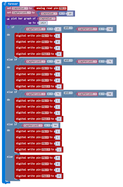
The experiment is about charging, but if the circuit is left the charge leaks from the capacitor and the percent charge drops, however the current programme does not show this discharge and the LED's don't turn off until the second switch is pressed and the capacitor discharges.

I modified the supplied programme to reflect this allowing the monitoring of charging and discharge to take place.

Modified Touch Develop Script

Improvement 2 - Adding serial data


The first improvement is not exactly rocket science but adds an extra element in the experiment to demonstrate charging and discharging of the capacitor.

The BBC Micro:bit can output serial data to to a host PC via the USB connection. It requires a drive from mbed. The instructions can be found on the coding the microbit site

You must install a device driver (for the computer to recognise the serial interface of the micro:bit); then, you must also install a terminal emulator (which is going to connect to the micro:bit and read its output).

Follow the instructions at https://developer.mbed.org/handbook/Windows-serial-configuration to install the device driver.

ARMmbed are partners with the BBC on the Micro:bit project.

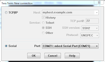
The connection from any terminal can be created using the following settings
  • Serial port : COM port that says “mbed Serial Port”
  • Baud rate: 115200.
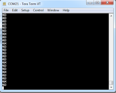
Any terminal will then list the data being sent from the Micro:bit

Selecting serial port

Setting baud rate

Viewing the data
To get the Micro:bit to send the data a new application was written. Using the Code for Microbit site and the block editing tooling available on it, each time led.plotBarGraph is called, the value is also written to the serial output.

CapacitorChargeSerialSend application

If you are using Chrome their is an easy way to capture the data within the coding tool.

You can use the Micro:bit extension to get serial data streaming in the editor.

  1. Install the Extension for BBC micro:bit on the Chrome Web Store.
  2. Restart Chrome and open the web editor
  3. The serial data will show below the simulator

Microsoft Micro:bit extension

LogView

The log view will automatically start to collect and organize the data it detects. Simply click on the log view to open the various options to export the data. The simplest option is to download the data as a CSV file. This file can easily be opened in programs like Office Excel.

In the data export dialog, there is another option to upload the data to the Azure cloud. This allows to upload small amounts of data without any kind setup. The data can be accessed via web services or directly from Office Excel.


Captured capacitor charge / discharge curves

Hopefully this gives you a test of what can be achieved easily with the BBC Micro:bit.

I will be following up with other articles in the future on this single board computer

Sunday 31 July 2016

What is a attack vector and what is the attack surface area

In this post I am aiming to explaining some of the common terms (such as attack vector, attack surface area) used when discussing cyber attacks in the way non-technical people can understand. In this post I'm using an example of a malicious PDF attack to explain the terms.

The scenario is an attacker sends an email with an attachment that is a malicious PDF the contains executable code if viewed on Adobe Reader, in this scenario the code will cause a denial of service.

The attacker will create a malicious payload in this scenario it is a PDF file that contains code that will take advantage of (exploit) the discovered vulnerability in a number of Adobe products. The PDF file is attached to an email which is then sent to the victim (could be a known individual in a targeted attack or to a large group of email addresses the attacker has obtained). The recipient would receive the email and the attacker is hoping that the PDF file will be opened by the recipient using a version of one of the affected Adobe products allowing the code to execute and cause a denial of service attack.

For the more technical I have based this on a actual reported vulnerability CVE-2016-1009 which affects Adobe Reader and Acrobat before 11.0.15, Acrobat and Acrobat Reader DC Classic before 15.006.30121, and Acrobat and Acrobat Reader DC Continuous before 15.010.20060 on Windows and OS X and allow attackers to execute arbitrary code or cause a denial of service (memory corruption) via unspecified vectors. [https://www.cvedetails.com/cve/CVE-2016-1009/] [https://helpx.adobe.com/security/products/acrobat/apsb16-09.html]

The scenario is illustrated in the diagram below.


The threat agent, attack, attack vector, vulnerability, exploit and attack surface area relating to this scenario are described in the table below.

Term
Definition
Example
Threat agent
an individual or group that can manifest a threat. It is fundamental to identify who would want to exploit the assets of a company, and how they might use them against the company
Attacker
Attack
Any kind of malicious activity that attempts to collect, disrupt, deny, degrade, or destroy information system resources or the information itself
Denial of Service
Attack vector
is a path or means by which a hacker (or cracker) can gain access to a computer or network server in order to deliver a payload or malicious outcome.
email
Vulnerability
Weakness in an information system, system security procedures, internal controls, or  implementation that could be exploited or triggered by a threat source.
Adobe Reader DC Classic (v15.006.30119)
Exploit
a piece of software, a chunk of data, or a sequence of commands that takes advantage of a bug or vulnerability in order to cause unintended or unanticipated behaviour to occur
Malicious PDF containing executable code that exploits CVE-2016-1009
Attack surface area
is the sum of the all vulnerabilities where an attacker can try malicious activity
All instances of the vulnerable version of Adobe Reader DC Classic (v15.006.30119)

Hopefully the scenario and the examples of what the terms mean in the context scenario help explain the usage of the terms by cyber security professionals.

In this scenario to defend themselves the victims need to identify if they are vulnerable and the attack surface area and then implement controls to remediate the vulnerability.

In order to identify if there are vulnerable organisations would need to know the software and version installed on all their assets (workstations, laptops, tablets, servers) and then monitor security feeds such as those from CERTS or Adobe to identify vulnerabilities within the assets as part of their vulnerability management programme. Alternatively they can conduct internal vulnerability assessments of their assets to identify vulnerabilities within them. This relies on the tool being able to identify the vulnerability (up to date signatures) and access rights to the assets to scan the installed software. A build review looking at security will only detect vulnerabilities within the build and not within software installed or updated by users after the build has been deployed.

Once a vulnerability has been discovered the attack surface area for that vulnerability can be identified by examining all assets for affected software.

This attack can be remediated by implementing the following

  • Software patching programme to ensure all security patches and updates are installed as soon as possible after release by vendors but after testing to ensure no unforeseen side affects
  • A vulnerability monitoring programme to identify when vulnerabilities become publicly notified
  • The use of anti-malware software with updated signatures and scanning engine to scan all incoming attachments.
  • User education to ensure users are aware of the danger of viewing attachments on unexpected emails.

These are covered by the CIS Critical Security Controls

CSC 2: Inventory of Authorized and Unauthorized Software
CSC 4: Continuous Vulnerability Assessment and Remediation
CSC 8: Malware Defenses
CSC 17: Security Skills Assessment and Appropriate Training to Fill Gaps
CSC 19: Incident Response and Management